Stabilizing the Spine: Fixation of operated segments
Pedicle Screws
Now that the interbody spacer and bone graft is in place, the next step is to put in screws and rods to prevent that spacer from popping out by maintaining the position of the spinal bones while the bony healing is occurring.
This page shows how the screws and rods can be placed without making open incisions, but by using minimally invasive techniques and landmarks that can be seen on X-ray
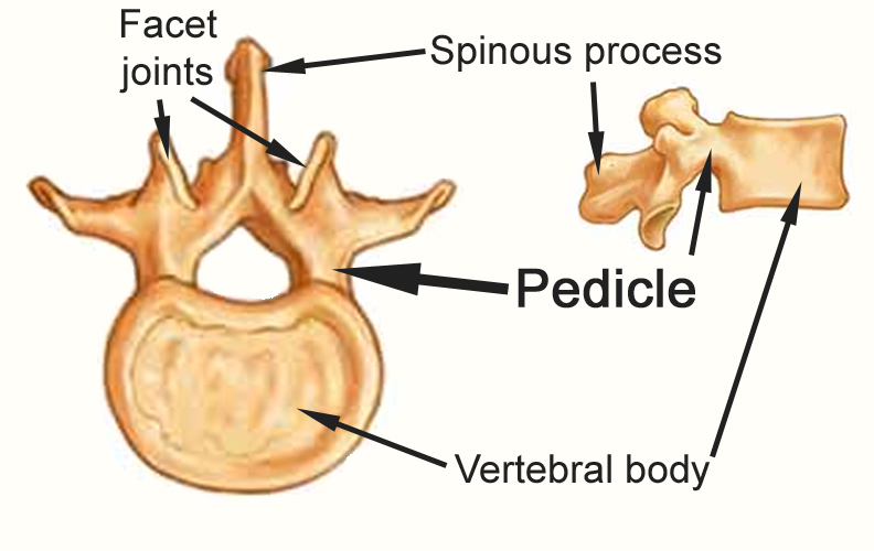
The screws that are placed are called “pedicle screws” since they go through a part of the vertebral bone called the pedicle, pictured here.
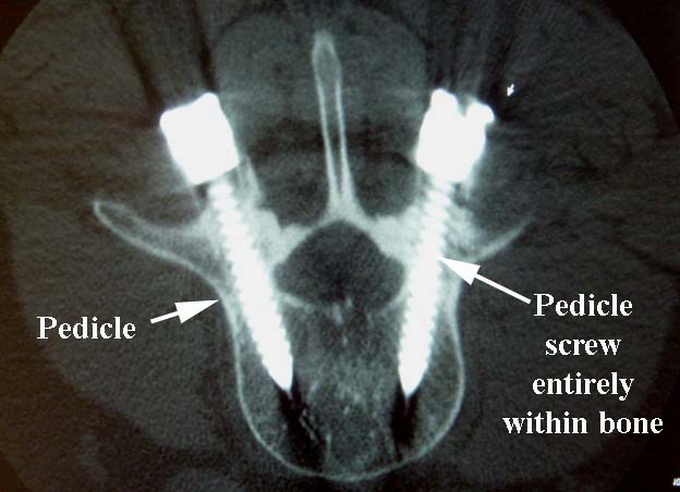
Here is an example of pedicle screws. If these screws are placed too far toward the midline, they can damage nerves. If they are placed too far from the midline, they will miss the bone and have no fixation, and can also damage soft tissue structures.
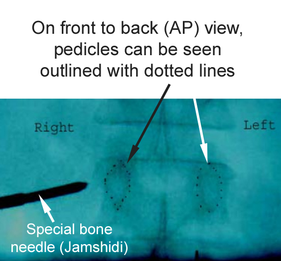
Placement of these pedicle screws is possible since the pedicle can be seen on the X-rays that can be taken in the operating room (fluoroscopy).
On this fluoroscopic front to back view (called an AP view), the pedicles can be seen outlined with a dotted black line. The needle is being introduced from the right.
Once the needle is placed, a guidewire can be passed through the needle. This wire marks a path for the screw to be placed into the spine bone in a safe manner, with minimal risk of injuring a nerve
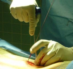
After the wires are placed, the path for the screw is tapped, and then the screw can be safely advanced into the bone, with very little danger of injuring a nerve.
Also, as part of the preparation for passage of the screws, the tap, which creates the pathway for the screw threads, is stimulated with low level electric current. If the metal threads of the tap are too close to the nerves, the surgeon will be alerted and can change the screw position.
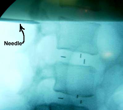
On the side view (called lateral view), the top and bottom of the pedicle can be seen, with the needle pointed to enter the pedicle.
Note the metallic markers that can be seen within the spacer that was placed between the vertebral bodies at each level in this case.
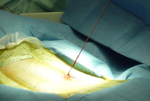
The second wire is placed in a similar fashion.
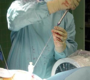
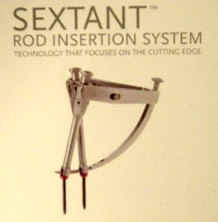
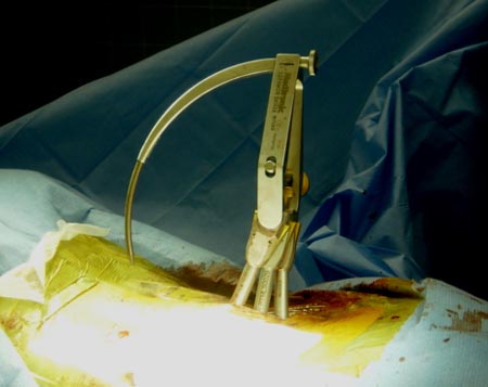
Once the screws are in place, a rod had to be passed to connect the screws. There are various systems on the market, but the diagram here illustrates the Sextant System by Medtronic which allows the rod to be placed between the screw heads with only a small incision.
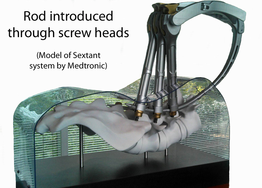
Here the Sextant is poised to deliver the rod to the screw heads. This action can be done through a small opening.
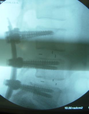
Finished construct, lateral (side) view. Again, note that the screws are within the bony margins of the pedicles.
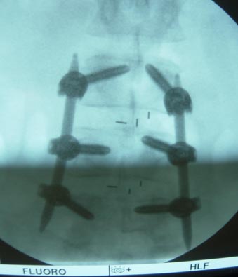
Here is the finished construct, AP (front to back) view. Note that the screws are in the pedicles, and the metallic markers in the interbody spacers show that these spacers are not too far to one side or the other.
Here are the incisions used to do this surgery on the left, and the dressings pictured on the right. The sutures are the type that dissolve, so no suture removal is required.

After the surgery, the patient is advised to wear a supportive lumbar brace for 2-3 months. This brace helps avoid stress to the pedicle screws, and helps maintain lordosis (hollow shape) of the low back.

To return to first page: Min Invasive Lumbar Fusion, page 1
To return to previous page: Min Invasive Lumbar Fusion, page 2
Lumbar Fusion Case Examples (including some done with min invasive technique)
